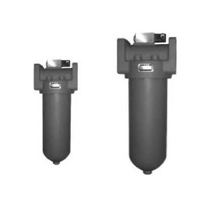
Gu-h With Check Valve Pressure Line Filter Series
It is mounted on the pressure line of the hydraulic system and is used to remove or stop the mechanical impurities mixed into the hydraulic oil and the Gum, pitch, carbon residue, etc. produced by the hydraulic chemical reaction itself, prevent the valve core jam, throttle hole, gap and damping hole plug and hydraulic components too fast wear, and other failures. The dropper is equipped with a pressure difference transmitter. When the temperature core is blocked by pollution to the pressure difference of the oil inlet and outlet is 0.35 MPA, the switch signal is sent out. The leakage core should be cleaned or replaced to ensure the safety of the system. The by-pass upper return valve can be opened automatically when the leakage core is plugged up to 0.4 MPA, or when the pressure difference between the inlet and outlet of the superheater is too large due to other reasons, in order to prevent It system oil backflow and prevent the pressure pipeline oil, loss, to avoid air and pollutants into the system, but also can make the oil reverse non-over-temperature flow, the reverse flow for the nominal flow of the chimney. The leaking core is made of a new type of chemical filter material, so it has the advantages of high over-temperature precision, high oil-passing capacity, small original pressure loss and large pollution-holding capacity, nN99.5% , ISO compliant.
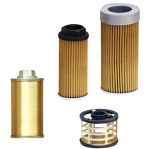
GU-H series filters are high pressure type and used in the pressure line of hydraulic system. Filter element is made of glass fibre.This new filter media has high efficiency and large dirt capacity.The absolute filtration is high.beta ratio is over 100.
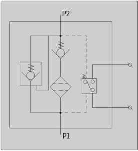
The differential pressure indicator signals when pressure drop across element reaches 0.35MPa. As the pressure drop rises to 0.4MPa,the by-pass valve in this filter will open allowing oil flowing directly. When the element being changed or cleaned, the oil of system can counter flow to prevent air and contaminant entering the system.The counter flow has not been filtered and is quarter of this filter flow rate.
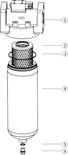
|
Number |
Name |
Note |
|
1 |
Fliter head | |
|
2 |
Element | Wearing parts |
|
3 |
O-ring | Wearing parts |
|
4 |
Housing | |
|
5 |
O-ring | Wearing parts |
|
6 |
Screw |
With check valve pressure line filter
BH:Water-glycol Omit if use hydraulic oil
Pressure class H:32MPa
Flow rate(L/min)
P:With CMS indicator
Omit if without indicator
Omit if threaded connection
F5 Flanged connection
Q:Glass fibre
Omit Paper
Filtration accu acy( p ni)
| loss(MPa) | By-pass setting (MPa) | Indicator power | Weight (Kg) |
Modelof element |
Connect |
| Max | |||||
| 0.35 | 0.4 | 24V/48W220V/50W | 3.9 | GX-10 x * | Threaded |
| 5.3 | GX-25 x * | ||||
| 8.4 | GX-40 x * | ||||
| 10.2 | GX-63 x * | ||||
| 12.4 | GX-100 x * | ||||
| 18.7 | GX-160 x | ||||
| 23.5 | GX-250 x | Flanged | |||
| 39.4 | GX-400 x * | ||||
| 42.6 | GX-630 x * |
| Model | Dia.(mm) | Flow rate (L/min) | Filtr.(M ni) |
Press. (MPa) |
Pressure |
| Intial | |||||
| GU-H10x*p | 15 | 10 | 35
10 20 30 40 |
32 | 0.08 |
| GU-H25x*p | 25 | ||||
| GU-H40 x Big p | 20 | 40 | |||
| GU-H63x*p | 63 | 0.1 | |||
| GU-H100X Big | 25 | 100 | |||
| GU-H160x*p | 32 | 160 | 0.15 | ||
| GU-H250 x*p | 40 | 250 | |||
| GU-H400x*p | 50 | 400 | 0.2 | ||
| GU-H630x*P | 53 | 630 |
Note:* is represents filtration. If the filter fluid is water-glycol, usage pressure 32MPa、 flower rate 63 Mm in x filtration accuracy 10 p m and the filter equipped with CMS ind icator. The model of the filter is GU • BH-H63 x 10P,the modelof element is GX • BH-63 x 10, if filter media is glass fibre, The model of the Filter is GU • BH-H63 x 10 QP, That of the element is GX • BH-H63 x 10 Q
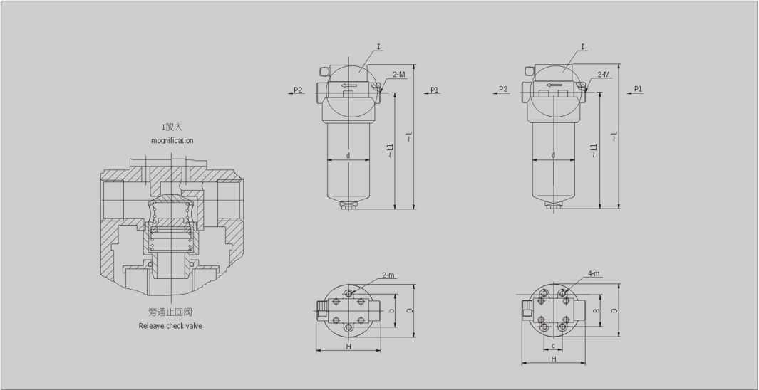
| Model | Size (mm) | ||||||||
| 〜L | 〜LL | H | b | c | D | D | M |
m |
|
| GU-H10 x *p | 220 | 160 | 118 | 70 | Φ88 | Φ73 | M27 x 2 | M6 | |
| GU-H25X *p | 310 | 250 | |||||||
| GU-H40 x *p | 306 | 237 | 128 | 86 | 44 | Φ124 | Φ102 | M33 x 2 | M10 |
| GU-H63 x *p | 361 | 295 | |||||||
| GU-H100 x *p | 429 | 357 | M42 x 2 | ||||||
| GU-H160 x *p | 468 | 393 | 166 | 100 | 60 | Φ146 | Φ121 | M48 x 2 | |
| Hydraulic filte | Size (mm) | ||||||||
| 〜H | 〜h | L | c | b | D | d | d1 |
m |
|
| GU-H250 x* F P | 534 | 457 | 166 | 60 | 100 | 146 | 121 | Φ40 | MIO |
| GU-H400 x * F P | 585 | 498 | 206 | 123 | 170 | 146 | Φ50 | M12 | |
| GU-H630 x * F P | 689 | 600 | 128 | Φ55 | |||||
note:please manufacture the connecting flange as ZU-H series.(page 68)


