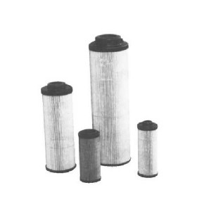
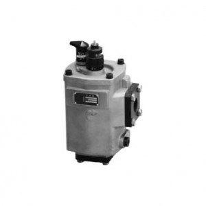
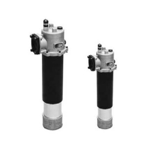
Nju Tank Mounted Suction Filter Series
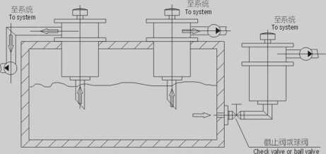
The NJU-series filters are widely used in hydraulic systems. The filter can be installed on the top or at the side of the tank. The filter head should be out of tank a- nd the filter bowl should be inserted from side or top of the tank into oil. The outlet is connected with pump outlet.25~160 Mmin type has combine removable flange, the working height can be adjusted in order to make the tank totally obdurate and that way can prevent the contamination from getting into the tank. During maintenance, open the filter cover, take out the filter element together with sludge cup and clean them. A by-pass valve and a vacuum are incorporated with the filter. When the pressure drop across the filter element reaches O.OIBmpa, the indicator gives signals showing maintenance shall be done. If no service is done and as the pressure drop rises to 0.02Mpa, the by-pass valve will open to ensure oil flow into pump.
1. Easy to install and connect: The superheater can be installed on the top of the tank cover plate or the Camber, the temperature head of the dropper is exposed outside the tank, the oil suction pipe is inserted into the oil surface from the top or side of the tank, and the oil outlet is connected with the pump suction and the oil outlet, the 25-160L/Min Specification is provided with combined movable Flange, the connecting height can be adjusted up and down, so as to realize the complete sealing of the oil tank and further prevent pollutants from entering the oil tank.
2. Easy to clean or replace the drain core: When the temperature core needs to be cleaned or replaced, it is convenient to open the upper cover of the over-temperature device, remove the drain core and wash or replace it together with the Dirt Cup, clean or replace it again, put it in, then the cover can be put into use.
3. With by-pass Valve: When the temperature core is blocked by contaminants to the vacuum degree of oil 0.018 MPA, the transmitter will send out a signal, should replace or clean the dripping core in time. If at this point can not immediately stop or no, people to replace the leakage core, set in the temperature core at the top of the oil bypass valve will automatically open (open pressure: vacuum 0.02 MPA) , to avoid the failure such as suction pump.
4. The transmitter is provided with a drain core to block the transmitter: The transmitter is mounted on the cap of the dropper. When the dropper is gradually blocked, the vacuum and contamination of the outlet of the thermometer can be observed from the visual mirror of the transmitter, at the same time, it can also receive electric reverse signal (sending signal value: vacuum 0.018 MPA).
5. With the Fouling Cup: The working medium flows through the dropping core cavity to obstruct the contaminants in the leaking core cavity and concentrate them in the fouling cup. Need to clean or replace the warm core. The Accumulated Contamination Cup is brought out with the dropping core, and the leakage of pollutants will not occur due to the replacement of the temperature core to make the pollutants heavy, new drop into the oil slightly phenomenon.

|
Number |
Name |
Note |
|
1 |
Bolt | |
|
2 |
Cap | |
|
3 |
Spring | |
|
4 |
Spring Seat | |
|
5 |
Element | Wearing parts |
|
6 |
O-ring | Wearing parts |
|
7 |
Housing | |
|
8 |
Seal | Wearing parts |
Tank mounted suction filter series
(L/min) Flow rate(um) Filtration acBH :Water-glycol Omit if use hydraulic oil
Y:WDC24V
With ZKF-II indicator
C:W220V
With ZS-1 indicator
Omit if without indicator
L:Threaded connection
F:Flanged connection
|
Model |
Flow rate (L/min) |
Filtr. (M ni) |
Dia. (mm) |
Initial AP (MPa) |
Indicator (V) (A) |
Connecting |
Weight (Kg) |
Model of element | |
| cNJU-25 x *L- y |
25 |
80 100 180 |
15 |
< 0.007 |
1224
36 220 |
2.5 2 1.5 0.25 |
Thread |
3.1 | UX - 25 x * |
| cNJU-40 x *L- y |
40 |
20 | 3.8 | UX - 40 x * | |||||
| cNJU-63x*L- y |
63 |
25 | 6.0 | UX - 63 x * | |||||
| cNJU - 100 x *L-y | 100 | 32 | 6.7 | UX -100X * | |||||
| cNJU - 160 x *L-y | 160 | 40 | 7.3 | UX -160x * | |||||
| cNJU- 250 x *F-y | 250 | 50 |
<0.01 |
Flange |
12.8 | UX -250x * | |||
| cNJU-400 x *F-y | 400 | 60 | 16.0 | UX -400x * | |||||
| cNJU- 630 x *F-y | 630 | 80 | 18.0 | UX -630x * | |||||
| cNJU - 800 x *F -y | 800 | 90 | 19.0 | UX -800x * | |||||
Note:*isfiltration accuracy, If the medium is water-glycol, flow rate is 160L/min, filtration accuracy is 80 u m, withZS-I indicator, the model of this filter is NJU - BH-160 x 80L-C, the model of element
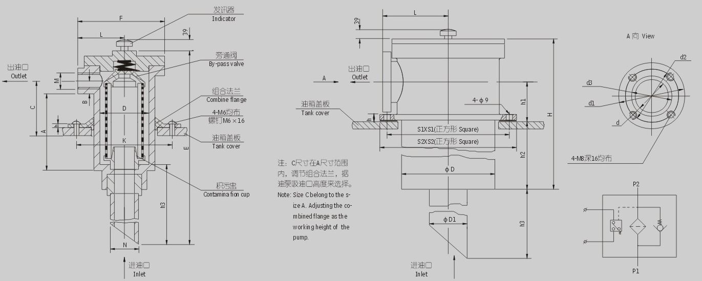
Table 1:NJU-25-160 Table 1: NJU-25-160 Threaded Connection
is UX • BH-160 x 80
1. NJU-25〜160(Table L)
|
Model |
Thread
M |
A |
B |
h3 |
E |
F |
L |
D |
K |
N |
h |
| cNJU-25 x*L- y |
M22X1.5 |
123 |
23 |
255 |
453 |
102 |
53 |
Φ72 |
Φ95 |
Φ25 |
6 |
| cNJU-40x*L- y | M27 x 2 | 153 |
23 |
482 | |||||||
| cNJU-63x*L- y | M33 x 2 | 174 |
28 |
385 |
637 |
122 |
65 |
Φ89 | Φ115 | Φ38 |
6 |
| cNJU-100x*L-y | M42 x 2 | 212 |
33 |
687 | |||||||
| cNJU-160x*L-y | M48 x 2 | 257 |
35 |
737 |
Table 2:NJU-250~800 Table 2: NJU-250~800 Flanged Connection
2. NJU-250-800(Table 2.)
|
Model |
(1 |
(11 |
(12 |
d3 |
D |
SI |
S2 |
hl |
h2 |
h3 |
H |
DI |
L |
h |
| c
NJU-250x*F-y |
50 | 100 |
84 |
60 | 122 | 160 | 180 | 67 | 256 | 402 | 392 | 60 |
98 |
16 |
| c
NJU-400x*F-y |
60 | 115 |
99 |
70 | 142 | 180 | 200 | 75 | 271 | 407 | 419 | 70 | 110 | 16 |
| c
NJU-630x*F-y |
80 | 130 |
114 |
90 | 162 | 200 | 220 | 82 | 279 | 517 | 440 | 90 | 120 | 16 |
| c
NJU-800x*F-y |
90 | 140 |
124 |
104 |
182 | 240 | 260 | 90 | 289 | 534 | 466 | 102 |
131.5 |
16 |
Note: The outlet flange, seal, screw and suction tube used for this series will be supplied by our plant. The customer only need welding the steel tube d3.


