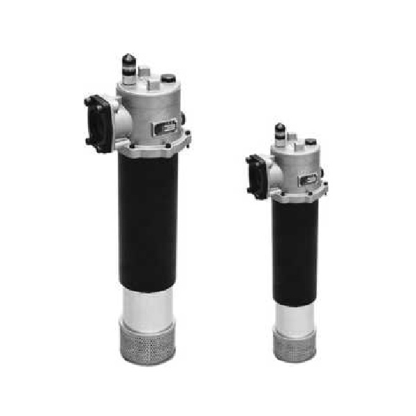
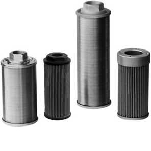
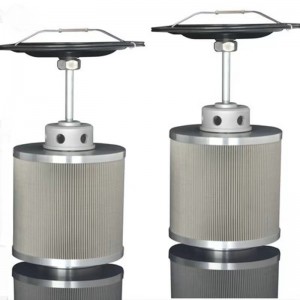
Rfb With Check Valve Magnetic Return Filter Series
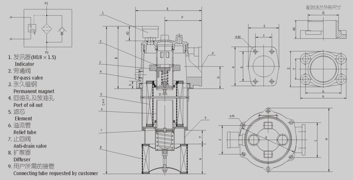
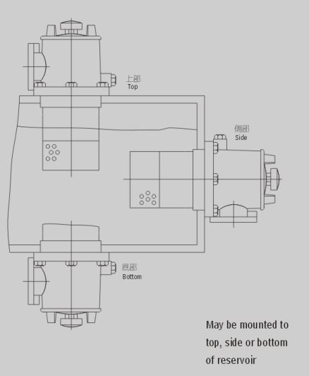
RFB-series filters are used in the return line of hydraulic systems. They can be installed on the top. at the side or in the bottom of tanks. Every filter is equiped with a permanent magnet to remove ferrous matters in the oil. Filter element is made of non-woven fib re with high efficiency and low restriction. A diffuser is fitted in the lower part of the filter, ensuring steady oil flow into the tank. There is a check valve in the f- iIter to prevent oil flowing out from the tank when filter element is changed.
The differential pressure indicator will signa I when the pressure drop across filter element attains 0.35MPa and the by-pass valve opens at 0.4MPa
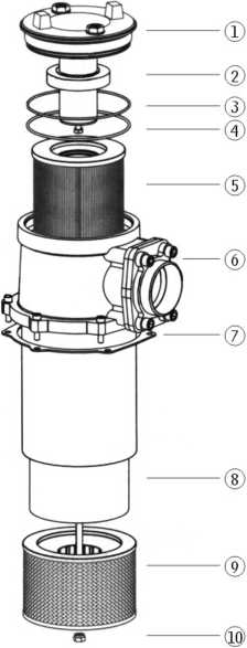
|
Number |
Name |
Note |
|
1 |
Cap Components | |
|
2 |
Ma ng net ring | |
|
3 |
O-ring | Wearing parts |
|
4 |
O-ring | Wearing parts |
|
5 |
Element | Wearing parts |
|
6 |
Housing | |
|
7 |
Seal | Wearing parts |
|
8 |
Connecting tube | |
|
9 |
Diffuser | |
|
10 |
Nut |
1. The over-heater can be directly installed on the top, side or bottom of the tank, the temperature head of the over-dropper is exposed to the oil, the outside of the tank, and the barrel part is immersed in the tank, thus simplifying the system piping and making the system layout more compact.
2. The superheater is equipped with permanent magnet, which can drop the ferromagnetic particles more than 1 Micron in the oil.
3. With by-pass Valve: When the cold oil starts, because the system liquid temperature is too low, the flow rate pulsates and so on the factor has been caused, the thermostat pressure difference is too big the main engine can not work, as well as the temperature core is blocked by the contaminant, under the temperature cover, the by-pass valve connected in parallel will automatically open, (the opening pressure difference is 0.4 MPA) to protect the dance and the system, the normal work.
4. With it return valve: The filter is placed on the side and bottom of the tank, when changing the temperature core, the oil will not flow out of the tank.
5. A liquid flow diffuser, which is composed of a liquid flow diffuser and the lower part of the cylinder body, enables the return oil to flow smoothly into the oil tank, preventing the formation of air bubbles, reducing the re-entry air, reducing the disturbance of the deposited and contaminated materials, and when the bypass valve is opened, it's stronger than a drip.
6. With a visual indicator and two-in-one transmitter, overflow tube, Fouling Cup: When the core gradually blocked, can be observed on the visual meter core blocking, at the same time, can also receive the signal (sending value is 0.35 MPA) . A overflow pipe and a Fouling Cup are arranged at the bottom of the temperature core, and the dropping core can be taken out together when replacing the dropping core, thereby avoiding the phenomenon of the contaminant falling back into the oil tank.
7. The dropping core is made of glass fiber, which has the advantages of high filtering precision, high oil permeability, small original pressure loss and large holding capacity. 3,10,20N200, ISO compliant.
8. For Drip, head and tank installation Flange, users can design and process 6 flange holes on the oil tank plate according to the size of the diagram. Unscrew the top cap to replace the drip core or fill the tank.。
9. There are two small oil return holes on the side and top of the temperature head of the dropper, which can be used for a small amount of oil in the system to return to the oil tank for overheating or a small amount of oil to the oil tank, and the filter is installed on the side or bottom of the oil tank, uNSCREW the small hole cover and put out the filter containing dirt, impurities of the oil, thus extending the service life of the core leakage, and is conducive to the purification of the oil.
Y:W DC24V WithCYB-I indicator
C:W 220V WithCY-II indicator
Omit if without indicator
Omit if without connecting tube
Y:Size Y of connecting tube as requested
(u ni) Filtration accuracy
BH:Water-glycol
Omit if use hydraulic oil
Checkvalve magnetic return filter
|
Model |
Flow rate (L/min) |
Filtr. (H m) |
Dia (mm) |
Pressure loss(MPa) | Indicator |
Weight (Kg) |
Model of element |
||
|
Initial |
Max. |
(V) |
(A) |
||||||
| RFB - 25 x * § |
25 |
1 3 5 10 20 30 |
1.6 |
W 0.075 |
0.35 |
1224
63 220 |
2.52
1.5 0.25 |
4.6 |
FBX 一 25 x * |
| RFB-40x*$ |
40 |
4.8 |
FBX-40X* | ||||||
| RFB - 63 x * y |
63 |
5.3 | FBX 一 63 x Big | ||||||
| RFB-lOOx*; |
100 |
6 |
FBX - 100 x * | ||||||
| RFB-160x*$ |
160 |
6.7 | FBX - 160 x * | ||||||
| RFB-250X 站 |
250 |
12.3 |
FBX - 250 x * | ||||||
| RFB-400X *§ |
400 |
14.7 |
FBX - 400 x* | ||||||
| RFB - 630 x * $ |
630 |
17.3 |
FBX - 630 x * | ||||||
| RFB - 800 x * |
800 |
18.6 |
FBX - 800 x * | ||||||
| RFB- 1000 x*$ |
1000 |
21.3 |
FBX - 1000 x Zev | ||||||
| RFB- 1300 x*$ |
1300 |
27.8 |
FBX - 1300 x Zev | ||||||
Note:*is filtration accuracy, If the medium is water-glycoljlow rate is 160L/min,filtration accuracy is 10 p m, with CYB-I indicator, the model of this filter isRFB . BH-160 x 10Y, the model of element is FBX • BH-160 x 10.
