Tf Tank Mounted Suction Filter Series
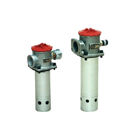
The overheater is installed at the oil suction port of the oil pump to protect the oil pump and other hydraulic components, so as to avoid inhaling pollution impurities, effectively control the pollution of the night pressure system, and improve the cleanliness of the hydraulic system.
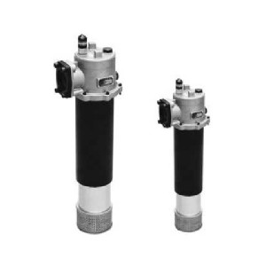
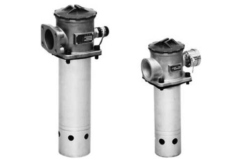
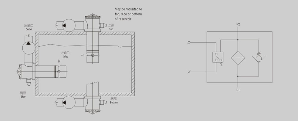
The overheater can be directly installed at the side, top or bottom of the oil tank. The oil suction cylinder is immersed below the liquid level in the oil tank. The temperature head of the overheater is exposed outside the oil tank. The overheater is equipped with self sealing valve, bypass valve, warming core pollution blocking transmitter and other devices, so that the oil in the oil tank will not flow out when replacing the dripping core and cleaning the warming core, This product has the advantages of novel design, convenient installation, large oil flow capacity, small resistance, convenient cleaning or replacing the core.
The TF-series filters can be installed on the top, at the side or in the bottom of t- he tank. There is a check valve inside the filter, during maintenance, when filter element is withdrawn for washing, the check valve will close automatically to stop oil f- lowing out from the tank.
A vacuum indicator in the filter gives signals when the pressure drop across the element reaches 0.018MPa showing that the filter shall be cleaned. If no maintenance is done, as the pressure drop rises to 0.02MPa, the by-pass valve will open to a- llow oilflowing into pump. This kind of filter can be installed at inlet port of the pump, in order to protect the pump and other component. This filter can help to keep hydr aulic system clean and easy to use.
1. Easy installation and connection, simplified system pipeline
The superheater can be directly installed on the side, bottom or upper part of the oil tank, the temperature head of the superheater is exposed outside the oil, the oil suction cylinder is immersed below the liquid level in the oil tank, the oil outlet is provided with pipe type and flange type connection, and the self sealing valve and other devices are set in the superheater, so that the pipeline is simplified and the installation is convenient.
2. Self sealing valve is set to make it very convenient to replace, clean the wick or maintain the system
When replacing, cleaning the dripping core or repairing the system, just loosen the end cover (cleaning cover) of the leakage detector. At this time, the self sealing valve will automatically close to isolate the oil circuit of the oil tank, so that the oil in the oil tank will not flow out, so that it is very convenient to clean, replace the warm core or repair the system. For example, opening the self sealing valve can be used to drain the oil slightly.
3. With warm core pollution transmitter and oil bypass valve, the reliability of hydraulic system is improved
When the leakage core is blocked by pollutants and the vacuum degree is 0.018mpa, the transmitter will send a signal, and the leakage core should be replaced or cleaned in time. If no one can stop the machine immediately or replace the drip core, the oil bypass valve on the upper part of the warm core will open automatically (the opening value is: vacuum 0.02MPa), so as to avoid the air suction failure of the oil pump. But at this time, it is necessary to stop the machine to replace or clean the dripping core, so as to maintain the cleanliness of the hydraulic system and improve the reliability of the hydraulic system.
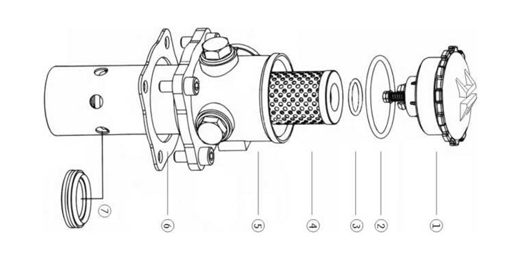
|
Number |
Name |
Note |
|
1 |
Cap Components | |
|
2 |
O-ring | wearing parts |
|
3 |
O-ring | wearing parts |
|
4 |
Element | wearing parts |
|
5 |
Housing | |
|
6 |
Seal | wearing parts |
|
7 |
Seal | wearing parts |

| Model | Flow rate (L/min) | Filtr.(H ni) | Dia.(mm) | Initial AP (MPa) | Indicator | Connecting | Weight (Kg) | Model of element | |
| (V) | (A) | ||||||||
| TF-25x*L - y | 25 | 15 | 0.4 | TFX-25X* | |||||
| TF-40x*L- y | 40 | 20 | Thread | 0.45 | TFX-40X* | ||||
| TF-63x*L- y | 63 | 25 | 12 | 2.5 | 0.82 | TFX・63x* | |||
| TF-100x*L-y | 100 | 80 | 32 | 0.87 | TFX-lOOx* | ||||
| TF-160x*L-y | 160 | 40 | 24 | 2 | 1.75 | TFX-160X* | |||
| TF-250x*f -y | 250 | 100 | 50 | <0.01 | 2.60 | TFX-250 X* | |||
| TF-400x*f -y | 400 | 65 | 36 | 1.5 | 4.3 | TFX-400X* | |||
| TF-630 x*F -y | 630 | 180 | 6.2 | TFX-630X* | |||||
| TF-800 x*F -y | 800 | 90 | 220 | 0.25 | Flange | 6.9 | TFX-800X* | ||
| TF-1000 X*F ~y | 1000 | 8 | TFX-1000 X* | ||||||
| TF-1300x*f -y | 1300 | 10.4 | TFX-1300 X* | ||||||
Note: * is filtration accuracy, If the medium is water-glycol, flow rate is IbOL/min, filtration accuracy is 80 um, with ZS-I indicator, the model of this filter is TF • BH-160 x 80L-C, the model of element is TFX • BH-160 x 80.
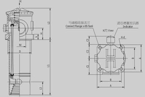
Threaded Connection
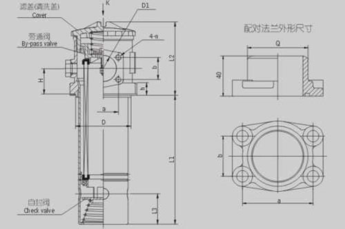
Flanged Connection
Table 1: TF-25-160 Threaded Connection
| Model | Size (mm) | ||||||||||||
| LI | L2 | L3 | H | M | D | A | B | Cl | C2 | C3 | h | 1 | |
| TF-25x*L - $ | 93 | 78 | 36 | 25 | M22X1.5 | 62 | 80 | 60 | 45 | 42 | 42 | 9.5 | 9 |
| TFT0x*L - $ | no | M27 x 2 | |||||||||||
| TF-63x*L - $ | 138 | 98 | 40 | 33 | M33 x 2 | 75 | 90 | 70.7 | 54 | 47 | 10 | ||
| TF-100x*L-$ | 188 | M42 x 2 | |||||||||||
| TF-160x*L-§ | 200 | 119 | 53 | 42 | M48 x 2 | 91 | 105 | 81.3 | 62 | 53.5 | 12 | n | |
Table 2: TF-250-1300 Flanged Connection
|
Model |
Size (mm) |
||||||||||||||||
| LL | L2 | L3 | H | DI | D | a | I) | n | A | B | Cl | C2 | C3 |
h |
d |
Q | |
| TF-250x*F | 270 | 119 | 53 | 42 | 50 | 91 | 70 | 40 | M10 | 105 | 81.3 | 72.5 |
53.5 |
42 |
12 |
11 |
60 |
| TF-400x*F | 275 | 141 | 60 | 50 | 65 | 110 | 90 | 50 | 125 | 95.5 | 82.5 | 61 |
15 |
73 | |||
| TF-630x*F | 325 | 184 | 55 | 65 | 90 | 140 | 120 | 70 | 160 | 130 | 100 | 81 |
15 |
102 |
|||
| TF-800x*F | 385 | ||||||||||||||||
| TF-1000x*F | 485 | ||||||||||||||||
| TF-1300x*F | 680 | ||||||||||||||||
Note: The outlet flange, seal, screw used for this series will be supplied by our plant; the customer only need welding steel tube Q. Connection of the indicator is M18 x 1.5; wi thout an indicator, a plug with thread will be supplied.

